INSTRUCTIONS FOR BG-301 PRIMARY PAN SENSOR
for metal & plastic pans

WARNING WORK SAFE, READ THIS:
Failure to read and comply with all warnings, cautions, instructions prior to starting installation may cause personal injury and/or property damage and void warranty.
This device must be installed in accordance with manufacturer’s instructions. This must be in accordance with all applicable local plumbing, drainage, and electrical codes.
Remove electric shock hazard — DISCONNECT THE POWER BEFORE INSTALLING SWITCH to avoid electrical shock and/or equipment damage. Do not use on circuits exceeding 24 volts to avoid damage to switch, shock, or fire hazard. Switch must be connected to an isolated transformer with a max rating of 30VAC, 8A, and 100VA
In any installation where property damage and/or per might result from inoperative switch due to power outage, a back-up system(s) and or alarm should be installed.
The switch must only be installed by a licensed contractor or under the direct supervision of same. Condensation pan must be properly maintained after installation and be kept free from foreign objects, rust, or other obstructions that might interfere with the proper operation of the float switch.
INSTALL FLOAT SWITCH ON DRAIN PAN
(To ensure proper performance of product, instructions must be followed.)
- Disconnect power to unit at main panel. Disconnect power to the low voltage thermostat circuit.
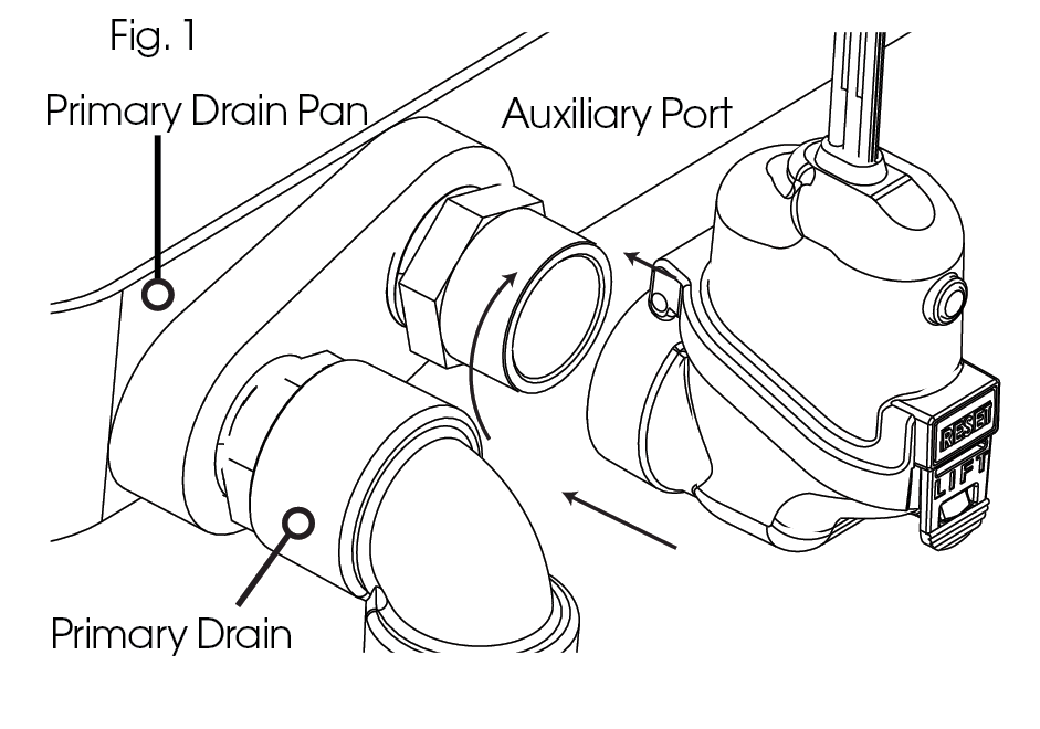
- Locate secondary condensate port on air handler.
- You have been supplied with 1 (one) pipe fitting connector. Apply pipe tape to male threads.
- Apply pipe tape to male threads
- Screw Fitting into Auxiliary Port. Use wrench to tighten. DO NOT OVER TIGHTEN.
- Attach main float to fitting on air handler hand tighten and then 1/8 turn with wrench. DO NOT OVER TIGHTEN
- Check to see if main float housing is level. If not — adjust threaded fitting with wrench to level float.
WIRING THE BG-301 IN A CONVENTIONAL HVAC SYSTEM
(To ensure proper performance of product, instructions must be followed.)

- Ensure the power is disconnected to the unit at the main panel prior to moving to the next step. Refer to the appliance manufacturer’s installation and operating instructions and also review wire layout in their instructions.
- Locate the Red wire coming from the 24 volt thermostat “R” terminal.
- Disconnect or cut red wire. Connect wire of the switch, using a wire nut, to the thermostat side of the circuit. Connect the other wire of the switch, using a wire nut, to the air handler side of the circuit or to the terminal in the unit. Incorporating both switch wires in the red circuit will shut the unit off (fig.2)
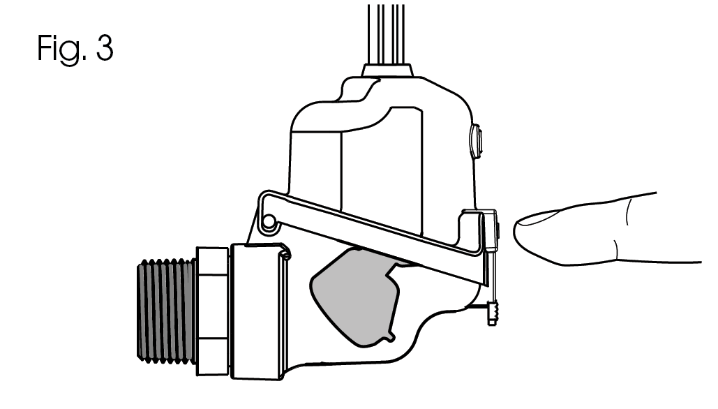
4. TEST THE SWITCH
Check that float is in the lower position. If its not, lower the float using your finger (Fig 3)
At start up, check initial average load
With unit on, test switch by raising float as shown. Unit should stop running if switch is correctly wired.
To test switch responsiveness fill pan with water to ensure that the switch stops the unit before the pan over flows. Remove the water.