
INSTRUCTIONS FOR BG-101 SECONDARY PAN SENSOR
for metal & plastic pans
WARNING: Work safe, READ THIS!
FAILURE TO READ AND COMPLY WITH ALL WARNINGS, CAUTIONS, INSTRUCTIONS PRIOR TO STARTING INSTALLATION MAY CAUSE PERSONAL INJURY AND/OR PROPERTY DAMAGE AND VOID WARRANTY.
This device must be installed in accordance with manufacturer’s instructions. This installation must be in accordance with all applicable local plumbing, drainage, and electrical codes.
Remove electric shock hazard — DISCONNECT THE POWER BEFORE INSTALLING SWITCH to avoid electrical shock and/or equipment damage. Do not use on circuits exceeding 24 volts to avoid damage to switch, shock, or fire hazard. Switch must be connected to an isolated transformer with a max rating of 30VAC, 8A, and 100VA
In any installation where property damage might result from inoperative switch due to power outage, a back-up system(s) and or alarm should be installed.
The switch must only be installed by a licensed contractor or under the direct supervision of same. Condensation pan must be properly maintained after installation and be kept free from foreign objects, rust, or other obstructions that might interfere with the proper operation of the float switch.
INSTALL FLOAT SWITCH ON DRAIN PAN
(To ensure proper performance of product, instructions must be followed.)
- Disconnect power to unit at main panel.
- Disconnect power to the low voltage thermostat circuit.
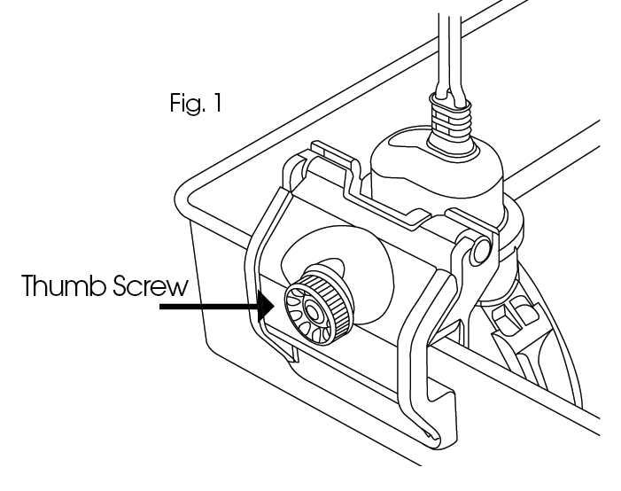
- Slide the float switch onto the side of the pan.
- Lightly secure the float switch by tightening the thumb screws (fig.1) Do not over tighten.
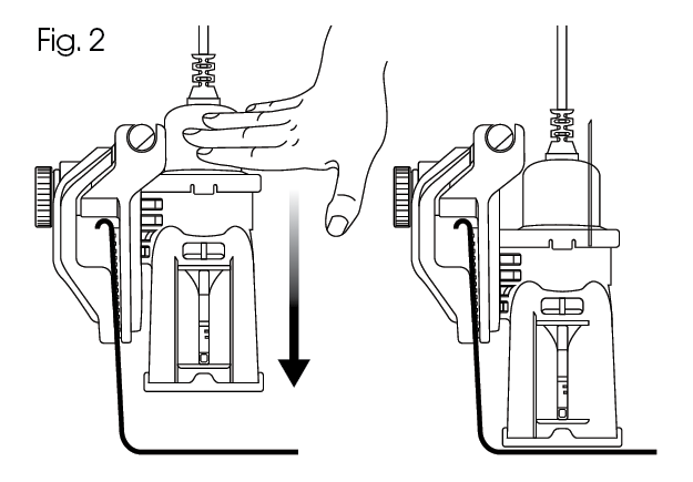
- Push down on the unit to adjust the depth to the bottom of the pan. (Fig. 2) Fits pans up to 3” deep.
- Finish tightening Thumb Screw.
TEST THE FLOAT SWITCH
A. Check that float is in the lower position. If its not, lower the float using your finger, as shown on (fig.4)
B. At start up, check initial average load
C. With unit on, test switch by raising float as shown. Unit should stop running if switch is correctly wired.
D.To test switch responsiveness fill pan with water to ensure that the switch stops the unit before the pan over flows. Remove the water.

INSTRUCTIONS FOR BG-301 PRIMARY PAN SENSOR
for metal & plastic pans
WARNING WORK SAFE, READ THIS:
Failure to read and comply with all warnings, cautions, instructions prior to starting installation may cause personal injury and/or property damage and void warranty.
This device must be installed in accordance with manufacturer’s instructions. This must be in accordance with all applicable local plumbing, drainage, and electrical codes.
Remove electric shock hazard — DISCONNECT THE POWER BEFORE INSTALLING SWITCH to avoid electrical shock and/or equipment damage. Do not use on circuits exceeding 24 volts to avoid damage to switch, shock, or fire hazard. Switch must be connected to an isolated transformer with a max rating of 30VAC, 8A, and 100VA
In any installation where property damage and/or per might result from inoperative switch due to power outage, a back-up system(s) and or alarm should be installed.
The switch must only be installed by a licensed contractor or under the direct supervision of same. Condensation pan must be properly maintained after installation and be kept free from foreign objects, rust, or other obstructions that might interfere with the proper operation of the float switch.
INSTALL FLOAT SWITCH ON DRAIN PAN
(To ensure proper performance of product, instructions must be followed.)
- Disconnect power to unit at main panel. Disconnect power to the low voltage thermostat circuit.
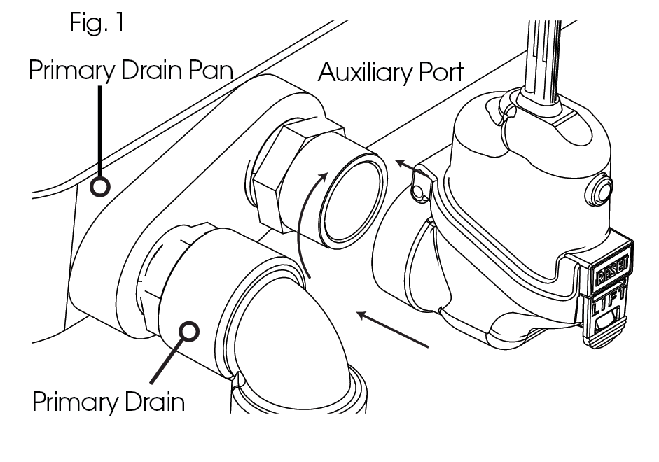
- Locate secondary condensate port on air handler.
- You have been supplied with 1 (one) pipe fitting connector. Apply pipe tape to male threads.
- Apply pipe tape to male threads
- Screw Fitting into Auxiliary Port. Use wrench to tighten. DO NOT OVER TIGHTEN.
- Attach main float to fitting on air handler hand tighten and then 1/8 turn with wrench. DO NOT OVER TIGHTEN
- Check to see if main float housing is level. If not — adjust threaded fitting with wrench to level float.
WIRING THE BG-301 IN A CONVENTIONAL HVAC SYSTEM
(To ensure proper performance of product, instructions must be followed.)

- Ensure the power is disconnected to the unit at the main panel prior to moving to the next step. Refer to the appliance manufacturer’s installation and operating instructions and also review wire layout in their instructions.
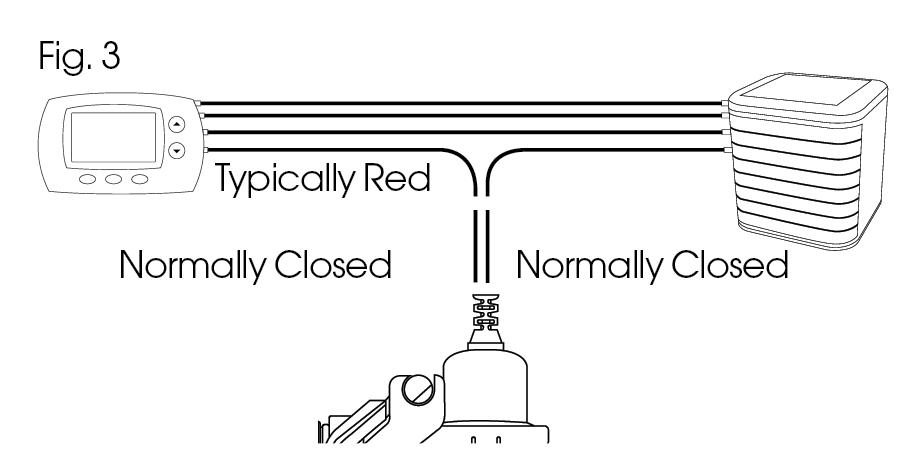
- Locate the Red wire coming from the 24 volt thermostat “R” terminal.
- Disconnect or cut red wire. Connect wire of the switch, using a wire nut, to the thermostat side of the circuit. Connect the other wire of the switch, using a wire nut, to the air handler side of the circuit or to the terminal in the unit. Incorporating both switch wires in the red circuit will shut the unit off (fig.2)
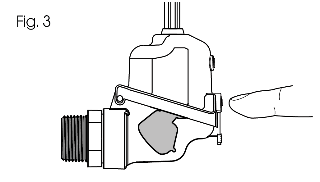
4. TEST THE SWITCH
Check that float is in the lower position. If its not, lower the float using your finger (Fig 3)
At start up, check initial average load
With unit on, test switch by raising float as shown. Unit should stop running if switch is correctly wired.
To test switch responsiveness fill pan with water to ensure that the switch stops the unit before the pan over flows. Remove the water.
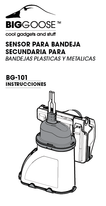
SENSOR PARA BANDEJA SECUNDARIA PARA BANDEJAS PLASTICAS Y METALICAS
Trabaje con seguridad,
LEA ESTO!
El no leer y cumplir con todas las advertencias, precauciones e instrucciones antes de comenzar la instalación puede causar lesiones personales y/o daños a la propiedad y anular la garantía.
Este dispositivo debe instalarse de acuerdo con las instrucciones del fabricante. Esto debe estar de acuerdo con todos los códigos locales aplicables de plomería, drenaje y electricidad.
Elimine el riesgo de descarga eléctrica – desesconecte la alimentación antes de instalar big goose para evitar descargas eléctricas y/o daños al equipo. No lo use en circuitos que excedan los 24 voltios para evitar daños al interruptor, choque o peligro de incendio. El dispositivo debe ser conectado a un transformador isolado que no exceda 30VAC, 8A, y 100VA
En cualquier instalación en la que se puedan producir daños a la propiedad y/o lesiones personales como resultado de un interruptor inoperante que se apague, se debe instalar un sistema de respaldo y/o una alarma.
El BG-101 sólo debe ser instalado por un contratista autorizado o bajo la supervisión directa del mismo. El recipiente de condensación debe ser mantenido adecuadamente después de su instalación y mantenerse libre de objetos extraños, óxido u otras obstrucciones que puedan interferir con el funcionamiento correcto del interruptor del flotador BigGoose BG-101.
INSTALACIÓN DEL BG-101 EN LA BANDEJA DE DRENAJE
(Para asegurar el correcto funcionamiento del producto, se deben seguir las instrucciones).
-
Desconecte la alimentación de la unidad en el panel principal.
-
Desconecte la alimentación del circuito del termostato de baja tensión.
-
Deslice el BG-101 en el lateral de la bandeja.
-
Asegure el BG-101 apretando el tornillo (fig.1). No apriete demasiado.
-
Mpuje hacia abajo la unidad para ajustar la profundidad al fondo de la bandeja.
-
Se adapta a bandeja de hasta 3“de profundidad (Fig.2)
-
Termine de apretar el tornillo de mariposa
CABLEADO DEL BG-101 EN UN SISTEMA HVAC CONVENCIONAL
CABLEADO DEL BG-101 EN UN SISTEMA HVAC CONVENCIONAL (Para asegurar el correcto funcionamiento del producto, se deben seguir las instrucciones).
Asegúrese de que la unidad esté desconectada de la corriente en el panel principal antes de pasar al paso 2. Consulte las instrucciones de instalación y funcionamiento del fabricante del aparato, así como la disposición de los cables en sus instrucciones.
Localice el cable rojo que viene del terminal del termostato de 24 voltios “R”.
NOTA: Si no esta presente, es recomendado que instale un fusible en linea para proteger el circuito de 24 voltios.
Desconecte o corte el cable rojo. Conecte uno de los cables largos del interruptor, usando una tuerca para cables, al lado del termostato del circuito. Conecte el otro cable largo del interruptor, usando una tuerca de cable, al lado del manejador de aire del circuito o a la terminal en la unidad. La incorporación de ambos cables en el circuito rojo apagará la unidad 2. (Fig. 3)
Prueba el Interruptor
Confirme que el flotador esta en la posicion baja. Si no lo esta, baje el flotador con el dedo (Fig. 4)
En la puesta en marcha la unidad HVAC, compruebe la carga media inicial Con la unidad HVAC encendida, pruebe el interruptor elevando el flotador como se muestra en la figura 3. La unidad debe dejar de funcionar si el interruptor está correctamente conectado. Una vez comprobado, baje el flotador
Para probar la capacidad de respuesta del interruptor, llene la bandeja con agua para asegurarse de que el interruptor detenga la unidad antes de que la bandeja se desborde. Retire el agua.
SENSOR PARA BANDEJA SECUNDARIA PARA BANDEJAS PLASTICAS Y METALICAS
Trabaje con seguridad, LEA ESTO
El no leer y cumplir con todas las advertencias, precauciones e instrucciones antes de comenzar la instalación puede causar lesiones personales y/o daños a la propiedad y anular la garantía.
Este dispositivo debe instalarse de acuerdo con las instrucciones del fabricante. Esto debe estar de acuerdo con todos los códigos locales aplicables de plomería, drenaje y electricidad.
Elimine el riesgo de descarga eléctrica – desesconecte la alimentación antes de instalar big goose para evitar descargas eléctricas y/o daños al equipo. No lo use en circuitos que excedan los 24 voltios para evitar daños al interruptor, choque o peligro de incendio. El dispositivo debe ser conectado a un transformador isolado que no exceda 30VAC, 8A, y 100VA
En algunas situaciones, el interruptor puede hacer que la unidad se encienda y apague rápidamente a medida que el nivel del agua sube lentamente en el recipiente. Después de un breve período de tiempo, la unidad se apagará completamente. El drenaje de condensación debe ser reparado si esto ocurre.
En cualquier instalación en la que se puedan producir daños a la propiedad y/o lesiones personales como resultado de un interruptor inoperante que se apague, se debe instalar un sistema de respaldo y/o una alarma.
El BG-301 sólo debe ser instalado por un contratista autorizado o bajo la supervisión directa del mismo. El recipiente de condensación debe ser mantenido adecuadamente después de su instalación y mantenerse libre de objetos extraños, óxido u otras obstrucciones que puedan interferir con el funcionamiento correcto del interruptor del flotador BigGoose BG-301.
INSTALACIÓN DEL BG-301 EN LA BANDEJA DE DRENAJE
(Para asegurar el correcto funcionamiento del producto, se deben seguir las instrucciones).
Desconecte la alimentación de la unidad en el panel principal.
Desconecte la alimentación del circuito del termostato de baja tensión.Deslice el BG-301 en el lateral de la bandeja.
Asegure los cables del BG-301 para que no afecten el funcionamiento.
Asegure el BG-301 apretando el tornillo (fig.1). No apriete demasiado.
CABLEADO DEL BG-301 EN UN SISTEMA HVAC CONVENCIONAL
(Para asegurar el correcto funcionamiento del producto, se deben seguir las instrucciones).
Asegúrese de que la unidad esté desconectada de la corriente en el panel principal antes de pasar al paso 2. Consulte las instrucciones de instalación y funcionamiento del fabricante del aparato, así como la disposición de los cables en sus instrucciones.
Localice el cable rojo que viene del terminal del termostato de 24 voltios “R”.
Desconecte o corte el cable rojo. Conecte el cable del interruptor, usando una tuerca para cables, al lado del termostato del circuito. Conecte el otro cable del interruptor, usando una tuerca de cable, al lado del manejador de aire del circuito o a la terminal en la unidad. La incorporación de ambos cables en el circuito rojo apagará la unidad (fig. 2).
Pruebe el interruptor.
Confirme que el flotador esta en la posicion baja. Si no lo esta, baje el flotador con el dedo (ver figura 3)
En la puesta en marcha la unidad HVAC, compruebe la carga media inicial
Con la unidad HVAC encendida, pruebe el interruptor elevando el flotador como se muestra en la figura 3. La unidad debe dejar de funcionar si el interruptor está correctamente conectado. Una vez comprobado, baje el flotador
Para probar la capacidad de respuesta del interruptor, llene la bandeja con agua para asegurarse de que el interruptor detenga la unidad antes de que la bandeja se desborde. Retire el agua.